Problems, Not Just on Transmission Lines
Charles Bayless recently retired as President and Provost of the West Virginia University Institute of Technology. Previously he was Chairman, President, and Chief Executive Officer of Illinova Corporation and its wholly owned subsidiary, Illinois Power Company. Prior to joining Illinova Corporation, he was Chairman, President, and Chief Executive Officer of Tucson Electric Power Company.
"Be Obscure Clearly" - E. B. White, The Elements of Style
In 2003 the National Academy of Engineering released its list of the greatest engineering achievements of the 20th century. In first place was the electric grid.
No part of the grid seems to be more obscure or misunderstood than reactive power. "It's like the head on a glass of beer," is one of the amusing descriptions of VARs. But to understand the operation, limitations and problems facing our transmission system as we transition to the greater use of renewables, an understanding of VARs is critical.
"VAR" stands for Volt-Ampere-Reactive. VARs come in two basic types, capacitive and inductive. Transmission and distribution lines both generate both types of VARs, while loads usually generate inductive VARs.
See Figure 1.
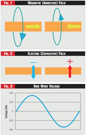 Figures 1, 2, and 3
If current flows through a line to the right as in Figure 1, then a magnetic field is set up circling the line as shown by the blue ellipse and the arrow.
If current flows in the other direction, as shown in Figure 1's other illustration, then the magnetic field is set up in the opposite direction. The first law of thermodynamics says energy can neither be created nor destroyed; in other words, there's no such thing as a free lunch. In each case, following the first law, energy from the line is consumed to set up the field.
See Figure 2.
While the current sets up a magnetic field, the line voltage sets up an electric field as shown in Figure 2, and the direction or polarity of the field is determined by whether the line voltage is positive or negative.
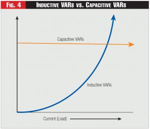 Figure 4 - Inductive VARs vs. Capacitive VARs
The problem with VARs comes from our use of alternating current (AC) where the voltage and current alternate back and forth in the shape of a sine wave, as shown in Figure 3, completing one cycle sixty times per second.
See Figure 3.
The magnetic and electric fields thus switch direction one hundred times per second, each time requiring energy from the line to set up the fields. The fields then collapse as the voltage and current begin to decrease to switch direction.
The net energy used to set up the fields can be thought of as the VARs.
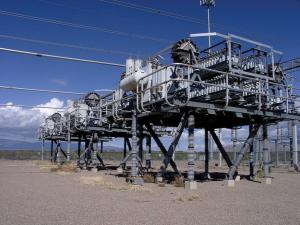 345 KV Series Capacitor, Tucson Electric Power
The capacitive VARs are represented by the energy used to set up the electric fields, while the inductive VARs are proportional to the energy used to set up the magnetic fields.
The first problem of VARs is then that we are sending energy hundreds of miles over a transmission line, only to use some of this energy to set up magnetic and electric fields.
The second problem comes from the word "reactive" and the collapsing fields.
An electric field is the type of field produced by a battery, so the collapsing electric fields are like thousands of tiny batteries distributed along the line. When the inductive field collapses, we have a changing magnetic field around a conductor.
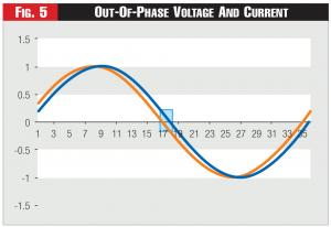 Figure 5 - Out-Of-Phase Voltage And Current
Fortunately, we already have a name for changing magnetic fields around a conductor: they are called a generator. So, as the magnetic fields collapse, we have thousands of tiny generators along the line.
As the fields build up they take energy from the line. As they collapse, each of these tiny batteries and generators inject voltage and current into the line as their energy flows back into the line.
This is where the head on a glass of beer analogy comes from; when the head disappears, it goes back into the beer. One might say, "Great, what's the problem, we are getting the energy back, why worry?" The problem is not that we are getting the energy back. It is when we are getting the energy back.
Unfortunately, the voltages and currents induced by either of the collapsing fields can add to or subtract from the desired line voltage and current. Under normal operating conditions, the capacitive field adds to the voltage and the magnetic field subtracts from the line voltage.
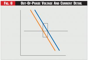 Figure 6 - Out-Of-Phase Voltage And Current Detail
So how do we correct for these effects? Fortunately, as the capacitive electric field is charging, the inductive magnetic field is discharging, and vice versa. Thus, if we can keep the two fields in balance, they will feed each other as they charge and discharge and their effects will cancel out.
Keeping these two fields in balance, however, requires constant attention to what is known as compensation. Compensation is the adding of inductors or capacitors to the line to achieve balance. The capacitive VARs on a line are a function of two variables, the capacitive reactance of the line and the line voltage.
The capacitive reactance is a physical property of the line and is determined by line design. As the voltage and capacitive reactance of the line are roughly constant at normal voltages, the capacitive VARs furnished by the line are relatively constant under normal operating conditions, as approximated in Figure 4.
See Figure 4.
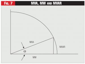 Figure 7 - MVA, MW and MVAR
The inductive VARs, however, are a different story. Inductive VARs generated on a line are determined by the inductive reactance, again a design feature, times the current squared. Thus they vary significantly as a function of current or load, as shown in Figure 4.
When a line is lightly loaded, the capacitive VARs far outweigh the inductive VARs. The voltage at the receiving end of the line is very high and out of limits and inductive VARs must be added to reduce the voltage.
As current increases, inductive VARs generated on the line gradually increase, offsetting the need for the added inductors until the inductance and capacitance are equal.
As current increases beyond that point, capacitors are quickly needed due to the current squared shape of the inductive VAR curve. A three hundred forty-five-kilovolt series capacitor bank at Tucson Electric is shown below.
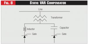 Figure 8 - Static VAR Compensator
It is interesting to note that the entire capacitor bank is supported on insulators and the entire apparatus, including the platform, is energized to three hundred forty-five kilovolts. This is an excellent reason to keep people who don't know what they are doing and who don't want to be vaporized from walking around in substations.
Compensation serves two basic functions: in transmission lines it maximizes the amount of real power that can be sent through the line. At loads where voltage has been decreased due to large inductive loads such as motors, it increases the voltage back to the specified voltage.
Let's start with transmission lines.
As mentioned above, when the fields collapse they induce voltages and currents different from the desired voltage and current. The effect is to throw the voltage and current out-of-phase.
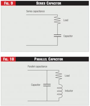 Figures 9 & 10 - Series and Parallel Capacitors
In AC transmission, the generator voltage is a sine wave with a frequency of sixty hertz, or fifty hertz in Europe and many other countries. The current in a perfectly balanced line should be in phase with the voltage and current, hitting maximum, minimum and zero values simultaneously.
See Figure 5.
As shown in Figure 5, the blue current plot is lagging slightly behind the orange voltage plot. The blue current line starts up from zero later and is always lagging the voltage. This is the graph of a circuit with too much inductance.
See Figure 6.
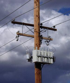 Switched Distribution Capacitors, Tucson Electric Power
If too much capacitance were present, the current would lead the voltage. Every freshman electrical engineering student learns the phrase "ELI the ICE man", where E (voltage) leads Current (I) in an inductive (L) circuit (ELI) while I leads E in a capacitive (C) Circuit (ICE).
The problem of voltage and current being out of phase comes from the time while one of the variables is positive and the other negative, as shown in Figure 6, which is an enlargement of a portion of Figure 5. As power equals voltage times current while one variable is positive and the other variable negative, that is, the area in the box, then power is negative.
One watt is one volt times one ampere (volt-ampere or VA). Due to the size of our generators we measure output in MVA.
The negative power represented by the box can be thought of as the VARs on the line. MVARs, MWs and MVAs do not add up as real numbers but add up at right angles, as shown in Figure 7.
See Figure 7.
As can be seen in Figure 7, MVA2=MW2+MVAR2 (Generator output squared equals mega VARs squared plus megawatts squared). The ratio of MW to MVA (Cosine ϴ) is called the power factor, and is required by regulations to be greater than 0.9 (usually).
The reason for this is that many customers have meters that measure volt-amperes. If customers are paying for volt-amperes but some portion of their power (VARs) can do no useful work, they are being short-changed. At power factors above 0.9, MWs are roughly equal to MVAs.
Figure 8 shows a VAR problem that affects transmission capacity. The MWs do not stretch all of the way out to the circle. If the line were perfectly compensated, then the angle ϴ would be zero and the MVA line would lie on the X-axis and MVA would equal MW.
Thus, by compensating the line we have increased the real power, or MWs, transfer capacity of the line. All of the generator power is thus being transmitted across the line and none of it is being consumed by the fields.
As capacitors and inductors are a lot cheaper than transmission lines and don't require twenty years to permit, it makes sense to compensate existing lines rather than build new ones. Further, if you can transmit extra MWs on a line at peak times, you don't need to generate those MWs again locally.
In the past, most of the variability in line current came from changes in load. Today change is coming from both ends of the line as we move to renewable energy, which is inherently variable.
These changes in generation lead to large changes in line current and thus large swings in VARs. These rapid swings dictate that adding and subtracting VARs manually is not fast enough to provide adequate compensation.
Thus, we are increasingly installing real-time VAR Compensation in the form of Static VAR Compensators (SVCs), a very simplified SVC schematic as shown in Figure 8.
See Figure 8.
An SVC has capacitors and inductors that are switched on and off by thyristors or other devices, that is, semiconductors that can be switched on and sometimes off in varying amounts by gate signals.
The line is monitored in real time and the amount of compensation needed is sent to the gating signals, which then smoothly and quickly vary from one hundred percent inductance to one hundred percent capacitance as needed.
Fixed capacitors and inductors are also usually used with SVCs to provide a base level of the needed reactance. In this way, the more expensive SVCs provide the fine-tuning while the fixed reactance provides the base.
Voltage variations and line optimization are not the only problems with VARs. Facilities that have large inductive power loads, usually motors that by their very design produce large magnetic fields, are said to consume reactive power. That is, they require large capacitive VARs to balance.
Facilities that have large capacitive power are said to supply reactive power. For most large industrial loads, either the utility or the customer installs capacitors to support voltage, as the collapse of an inductive field induces a voltage that lowers the line voltage and lags the current.
Capacitors do have one problem in supporting voltage. As the total reactive power supplied by capacitors is proportional to the line voltage, as voltage goes down the capacitors supply less reactive power, exactly the opposite of what is needed.
This isn't a problem as long as more capacitors can be switched onto the line, but if all of the capacitors are committed, it can be a fairly quick trip to voltage collapse.
Fortunately, we have devices to supply active VARs as compared to the passive VARs supplied by fixed capacitors. First, generators. Generators produce electric power by rotating a large electromagnet, the rotor, inside coils of wire called a stator.
The magnetic field of the rotor is produced by a current in the rotor. What happens if that current decreases? One's first guess might be that power output would go down. But energy can neither be created nor destroyed, so the energy in to the generator equals energy out, taking into account the losses.
What happens is that as the exciter current decreases, the power factor changes. The output power shifts from real power to reactive power with a very high inductive power factor.
The opposite happens if the rotor field current is increased; the generator begins supplying capacitive VARs. Thus, by over-exciting the generator, we can generate capacitive VARs that are not dependent on line voltage to provide voltage support.
Another device is called a synchronous condenser; capacitors are also called condensers. A synchronous condenser is simply a large motor with no load. As its field current varies it will consume or provide VARs as necessary, regardless of the line voltage.
Further, many modern solar and wind invertors can supply reactive power even when they are not generating. Mandating that renewables provide reactive support will speed their integration and lessen cost, versus supplying VARs externally.
If you live in a city such as Tucson that is at the end of long transmission lines, a local power plant or a synchronous condenser will be running during periods of high load to provide active VARs, even though cheaper plants are available elsewhere.
Given that generators and synchronous condensers can produce active VARs, why don't we just use them to produce all of our VARs? First, fixed capacitors are far cheaper to install and maintain. Second, you can't ship VARs.
The rise or fall of voltage across any section of a transmission or distribution line is proportional to the net VARs in the line. Thus, if we try to ship VARs from point A to point B, we will cause a rise or fall in the voltage in that section of the line. VARs must be produced near the place where they are needed.
The VAR problem is not limited to transmission lines, but extends all the way to the end of the distribution circuits.
The photo above shows capacitors on a distribution line. Some capacitor banks are permanently connected to the distribution line. But if all capacitors were permanently connected to the line, voltage would be too high during low load conditions.
The solution is switched capacitors. In the photo the little cylindrical object on the far side of the rectangular capacitors is a voltage-activated switch; only one switch is visible, and there is one for each phase. When the voltage falls to a predetermined level, the switch activates, connecting the capacitor bank to the line and raising the line voltage.
DC lines do not have the VAR problem, as their current and voltage is steady. But they have other drawbacks, such as the inability to use transformers to step the voltage up and down as required. As the cost of DC technology falls and the desirability of shipping renewable energy long distances grows, we will see more DC lines.
Additionally, DC lines transmit more power for the same voltage. In an AC line, voltage and current only hit peak momentarily. At all other times the voltage and current are lower, thus transmitting less power.
If a DC line is a three hundred-forty-five-kilovolt line, it is always at three hundred forty-five kilovolts and current is constant for any given power level.
Thus, a three hundred-forty-five-kilovolt line can transfer 1.414 times as much power as an AC line, for the same current.
And, DC lines usually only have two conductors, one for current going out and the other for current returning, rather than the three conductors needed for an AC line.
See Figure 9 and Figure 10.
Capacitors and inductors can be connected in series or in parallel. In a series capacitor, as shown in Figure 9, all the line current flows through the load. In a parallel capacitor, as shown in Figure 10, part of the line current flows through the capacitor, while part flows through the load.
Series capacitors are usually used for line compensation while parallel capacitors are usually used for voltage support.
As we make the necessary transition to renewables, variability and the need for VAR control will grow. Even if we manage to construct a high- capacity, nationwide DC grid to ship renewable power from locations like Arizona and North Dakota, we will still have increased variability on distribution circuits. That's because rooftop solar installations may generate from zero to one hundred percent. That variability will vastly increase the need for compensation on distribution lines.
However we proceed, the need to understand VARs will only increase.


